Click here for the image gallery.
Equipment
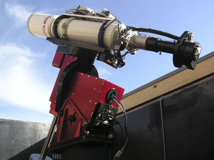
The observatory (shown above) is in our home in Scottsdale, AZ. Its major elements are: a Bisque Paramount ME mount and a Takahashi TOA-130 refractor, SBIG ST-10XME CCD camera with a Finger Lakes CFW-2 filter wheel and Astrodon LRGB (and Custom Scientific Ha and OIII) filters. With this combination the field of view is 34 x 51 arcmin. Therefore the major diagonal of the images is one degree. It produces a 1.4 arcsec/pixel illumination. My old LX-200 rig had a fork mount and I must admit that I do miss just coasting through the meridian without interrupting imaging because of the gyrations of moving the scope from the west to the east side of the pier that all German mounts must perform. But the precision - both guided and unguided - of the ME is unsurpassed by any other amateur mount as far as I know.
The summers here in Arizona have shown me that water cooling the ST-10 is an absolute necessity in a climate like this one. An aquarium water chiller puts (~50° F) water through the camera and enables it to regularly achieve -25° C pretty much any night of the year. The water cooling arrangement is not shown in the above photo. In mid-summer the night time temperature in the observatory is between 85°F and 90°F. Even under those conditions the chilled water allows the ST-10 to use only 74% to 78% of its internal cooling capacity. It runs with the fan turned off. I do have to watch the ambient wet bulb temperature (dew point) and make sure the cooling water is not colder than that. If the cooling water is colder than the dew point, condensation can form on and inside the camera (NOT good).
Autoguiding is achieved via the ME's DirectGuide software. This means that no cable is required between the camera and the mount's guider port. The TC-237H guider chip inside the ST-10 talks to CCDSoft; CCDSoft talks to TheSky6; and TheSky6 gives guiding commands to the mount.
Everything (except moving the roof) is controlled from a dedicated PC in my study. The mount is controlled by the PC through a separate dedicated serial cable. The PC sends and receives camera, filter and focus data using one cat 5 cable (the white cable shown in the above photo) via a USB extender (Icron Ranger) up, through the RA and Dec axes of the mount, to the top of the scope. (The blue USB cable shown in the photo is no longer there.) The Icron Ranger transmits USB signals to and from the RoboFocus, the ST-10, and the FLI filter wheel. The Robo Focus requires a serial connection so a USB-to-serial connector is used. My good friend John Smith designed this system (see the diagram at the bottom of this page) and I built it. Then John held my hand and helped me make sure everything worked. For this I am extremely thankful and seriously in his debt.
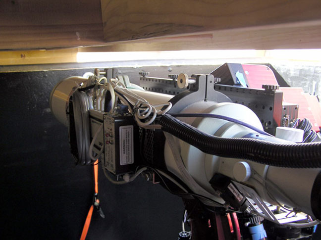
The scope is shown above in its Park position. Closest to the camera (on top of the scope) is the RoboFocus control box, then comes the Icron REX, then the DC-DC power supply for the ST-10XME camera. The 'dongle' for the FLI filter-wheel and a barrier strip to interconnect 12.5 V DC wires are hidden forward of the camera power supply. When calculating the required pier height, I used the diagram of the Paramount ME in the Bisque instruction manual to see what the height of the top edge of the parked Versa Plate would be at my latitude. What I didn't count on was the extra width of the telescope mounting rings AND the height of the top corner of the declination motor housing which is the highest point on the mount in this position. As you can see from the above photo, the sliding roof misses it by about an inch! I was VERY lucky. I had left enough room to spare in the final design - and I needed every bit of it.
Imaging and Processing Procedures
It's presumptuous of me to advise anyone else how to do things. But, I have learned to take lots of dark frames, as high quality flats as possible, and get LONG effective exposure times by taking many Light frames. Ron Wodaski says, "Think hours not minutes."
I use The Sky6, CCDSoft and CCDAutoPilot4 to obtain images. I find CCDAutoPilot4 to be extremely valuable in efficiently controlling an evening's imaging session. It also is a tremendous help in obtaining quality flat frames which are usually difficult to get and are crucial to good quality images. But, my absolute number one favorite piece of software is CCDStack written by Stan Moore and published by ccdware.com . This program takes in the stack of raw images (and the dark, bias, and flat frames), calibrates the light frames, rejects all sorts of noise, stacks them, and puts out either an LRGB or RGB final image. The color correction is simple, and produces a first class result. The whole program is intuitive, has an excellent on-line tutorial, and on-going email list where Stan tries to answer all reasonable questions. I used to spend hours in CCDSoft, MaximDL, Picture Window, and AIP4Win trying (usually in vain) to get decent color. Using CCDStack's well-designed, smooth process (for which several tutorials are available on-line) yields accurate, well-balanced color images.
The best 'trick' I have learned is - when aligning ('registering') the color frames, have the Luminance master in the stack as well, and align EACH R (or G, or B) frame to that Lum master. Then remove the Lum master from the stack and (mean) combine them to get either the R, G, or B master. This avoids putting the R, G, and B component frames through two somewhat destructive alignment processes which is unavoidable if I first make up the color masters and then align each of those color masters with the Lum master.
I send RGB and Lum (16 bit TIF) masters to PhotoshopCS2 from CCDStack. I use Noel Carboni's Photoshop Actions to improve the two images separately (get rid of background noise and increase saturation and star color in the RGB, use 'make stars smaller' and smart sharpen on the Lum), and only then do a luminosity layer combine in PS.
Software Help Files
Astro-imaging is a wonderful, rewarding hobby. It has a steep learning curve and the manuals or Help files that accompany most astro-software need improving in my opinion. For example, the procedure for setting up and performing a TPoint run using TheSky6, CCDSoft, and Automapper II is a magic-mystery tour for the uninitiated despite Ron Wodaski's explanation. When my expert imager friend, John Smith explained the process to me, I got through it. But I cannot find those steps he showed me presented in ANY software manuals or web forum.
Some websites to take a look at
Links to a few of my favorite imagers and their work are listed below. Not only are their results phenomenally beautiful, but these men have all made significant contributions to the art of CCD imaging and processing. There are any number of phenomenal imagers around, but these are on the absolute top of my list.
Robert Gendler developed the LLRGB image processing technique and produces unsurpassed quality images. He now makes heavy use of remote imaging techniques.
Noel Carboni has written a set of 'actions' for Photoshop that I find invaluable.
Dean Salman has a website with many interesting items and useful links. His procedure for creating mosaics using CCDStack is a singularly important contribution to astro-imaging. You can find it here. Click on the appropriate tab.
R Jay Gabany is one of the best and most prolific amateur astro-imagers. His website is full of powerfully processed images. At the bottom Jay has a list of links to most of the world's best amateur sites.
Good luck and all the best. May your skies be clear and dark. And above all, I hope you have fun.
Don Scott
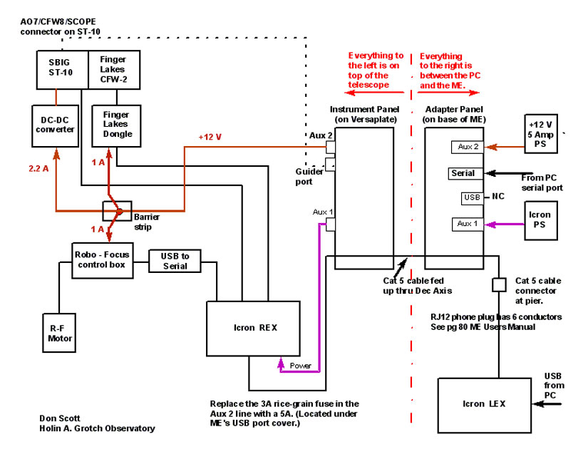
Electrical Diagram
Shown below is a schematic diagram of the electrical setup. The ME is driven by a serial cable from the PC's serial output port to the ME's serial input port. All other signals go on a single cable from the PC up through the LEX / REX to the top of the telescope. The REX has four USB output ports. Three of these ports are now used for the following signals: 1. RoboFocus (via a small USB to serial converter); 2. ST-10XME; 3. Color wheel. The fourth USB port will be used in the future for a camera rotator.
In an earlier setup, there was a USB cable running from the fourth USB output on the REX down to the ME USB input port to run the ME. Now the only cable running through the ME's axes is the Cat5 cable for the Icron. The fourth USB output port from the Icron REX is presently not used. My hope is to use it at a future date to control a camera rotator.
The guider cable from the camera to the guider-port is shown dotted because I do not use one. I use DirectGuide.
The two parts of the Icron hub extender are: LEX = Local extender box that sits on top of the PC, and REX = Remote extender box that is clamped to the top of the scope. These are connected by a Cat5 cable that is led up through the right ascension and declination axes of the mount.
The Aux 1 and Aux 2 ports on the ME are the two coaxial ports. These are used to carry the 12 V DC power lines: Aux 1 = For Icron (always powered up); Aux 2 = For everything else.